Our Projects
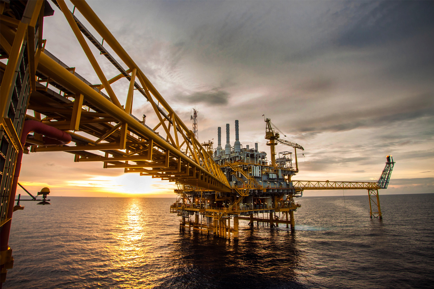
Ashrafi Water Injection Project
Al Ahlia is the main contractor for this “Ashrafi Water Injection Project” with EPS (Engineered Pipeline Systems) being a sub-contractor. This project is designed to filter, deaerate and chemically treat raw seawater and then provide suitable pressure for injection into the sub-sea formation for the purpose of maintaining reservoir pressure. Operating experience may modify some of the procedures.
Chemical Treatment
Experience of other operators in the area has shown that hypochlorite treatment of the seawater to kill algae as well as deoxygenation of the seawater is sufficient to reduce internal corrosion. Experience of other similar projects is documented.Continual monitoring of the system with both coupons and linear polarization resistance (LPR) probes will indicate if additional corrosion protection is necessary.
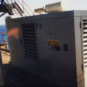
Electrical Power
The Caterpillar G3306EPG 80 kw generators will provide electric power for the lift pumps, PLC, controls, actuated valves and telemetry. One generator will provide sufficient power to operate one lift pump, and all ancillary electrical components of the facility. An automatic switching device will allow the second (standby) generator to come on line, should a failure of the first (primary) generator occur. This transfer should occur in 30 seconds or less. Company personnel will be able to designate which generator will be primary and which is standby. It is recommended that this function be alternated between generators on a monthly basis. The PLC and telemetry will include an UPS (uninterruptible power supply), which will enable communication to the company in the event of total generator failure.
Lift Pump
Agiba Personnel will designate which lift pump is primary and which will be pack up it is recommended that this function be alternated between pumps on a monthly basis. The casing for the lift pumps is recommended to extend to a depth of 50 feet (15.24 meters) below the water surface. This is as per the water tests reported in section 3 of the tender documents, and is the location of the best quality water. The lift pump will be set at a depth of 10 feet (3.05 meters) below the water surface. The operating lift pump will pump 35,000 BWPD (barrels of water per day) to the cellar deck platform. 5,000 BWPD will be utilized in the marine heat exchangers of the CAT G3412TA engines (2,500 BWPD per engine). The remaining 30,000 BWPD will flow to the NOWATA filter housing.
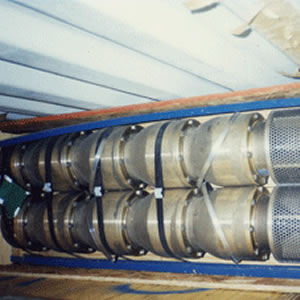
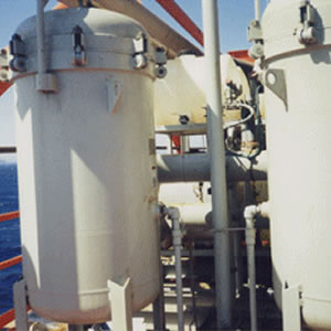
Nowata Filters
Two filter housings are provided. Upon initial operation of a housing with clean filters, the expected differential pressure across the filter housing is approximately 2 psi. As the filter cartridges become clogged with "dirt"' removed from the seawater, the differential pressure will increase. Once the differential pressure increases to 30 psi, the PLC will actuate the electric automatic valve actuator on the inlet butterfly valves of the filter housing. This electric valve actuator is linked to both inlet butterfly valves. As one valve is closed. the other valve is opened. Based on a water quality analysis, the outlet water from the filters will contain total suspended solids of less than 5 Microns in Size. Due to the range in differential pressure across the filters, the 0 pumps, being centrifugal, could have a varying output, with a greater flow at low differential pressure (dp) and lower output at high dp. The impact of this variable flow would be most critical at the oxygen desorption tower (ODT). Since the output of the ODT is the suction volume to the injection pumps, and this flow rate is a constant rate, based on engine/pump rpm, the increase flow at low dp could result in flooding of the ODT. To prevent this, a level sensor will be installed in the ODT. This sensor, through the PLC, will control an electric actuated throttling valve on the discharge of the lift pumps. This valve is located between the lift pumps and the filter housings. When the filters, are clean and the dp low, this valve will partially close, creating back pressure on the lift pumps and resulting in a constant water flow rate and level in the ODT. As the dp of the filters increases, this valve will open to provide additional pressure to the filters, while maintaining a constant flow rate and level in the ODT.
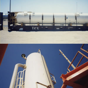
Oxygen Desorption Tower (ODT)
Oxygen desorption towers are used to remove oxygen from water prior to injection in secondary recovery installations. These towers are vertical vessel employing multiple trays where the water is counter currently contacted with a stripping gas. Oxygen desorption towers have been used effectively remove the oxygen content in water to less than 0.1 ppm. The water enters near the top of the column and flows down through the trays passing across each tray and then down the staggered down comers to the next tray. The water collects in the bottom of the column and the discharge is controlled by a liquid level control. The stripping gas enters the column near the bottom and passes upward through the float valves or rubble caps on the trays and strips the oxygen from the water. The gas passes out the top of the vessel through a stainless steel wire mesh mist extractor. Through a gas outlet line, and a gas back pressure valve. This column is designed at 50 psi W.P. however, it will be operated at 15 psig. Water from the filters will flow to the ODT. Water will enter the tower at at the 30 foot (9.15 meter) level Gas from the platform separator will enter the tower at the 13.75 foot (4.19 meter) level. This gas will be reduced from its normal operating pressure to 20 psig through the use of a gas pressure regulator. Actual gas flow will be determined by the consumption of the 2 CAT G3421TA engines and one generator. Calculated gas flow for proper tower operation is less than the required for the engines. The increased GWR (Gas water ratio) caused by the engine demand will increase the tower Oxygen removal efficiency. After the inlet gas pressure is reduced through the gas pressure regulator, the gas will flow through a NOWATA gas filters/Separator to remove any hydrocarbon liquids which may form due to pressure reduction. Two filters separators are furnished, one primary and one standby. Gas from the ODT will pass through a ball separator. This separator is sized to remove any free water which may be present in the gas leaving the ODT. And is equipped with a ball check valve in the outlet connection which will seal off all flow should the tower become flooded and water overflow into the outlet gas piping preventing water from being sent to the engine intakes.
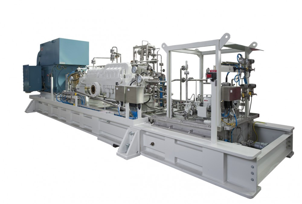
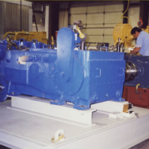
Injection Pumps
The two (2) injection pumps skids each consist of a CAT G3412TA engine, FALK 425A speed reducer, GASO T-600-7 triplex pump, and ancillary controls, dampeners, and valves. - The water from the ODT is piped to the suction inlet of each pump at 15 psi. - The discharge from each pump is sent directly to the well at 1000 psi. - The 5-3/4" plungers of the GASO pumps have a maximum pressure rating of 1370 psi. During normal operating parameters, each pump will move 15,000 BWPD (barrels of water per day). This will require the pumps to operate at 171 rpm and the engines to operate at 1410 rpm. A pressure transducer will be installed on the discharge piping to the well. This pressure transducer will send a signal to the PLC and will monitor the pressure to the well. If the pressure falls below 1000 psi, but is above 200 psi, the PLC will increase the engine speed. This will in turn increase the pump speed, increasing pump volume output. The PLC will attempt to maintain 1000 psi until the maximum engine rpm of 1800 is reached. The pump will then be operating at 218 rpm and will be pumping 19,000 BWPD. The possible reasons for the PLC to increase pump speed to maintain 1000 psi are: 1. One of the injection pumps/engines has failed. 2. The well does not require 1000 psi to accept 30,000 BWPD. If the injection pressure to the well exceeds 1000 psi, the PLC will alarm the company. At 1100 psi, the PLC will shut down one pump/engine. If the pressure reaches 1200 psi, the PLC will shut down the second pump/engine. The PLC will also monitor conditions of the engine, gear reduction unit, and pump, and will alarm the company and shut down the engine should a monitored condition indicate a failure.
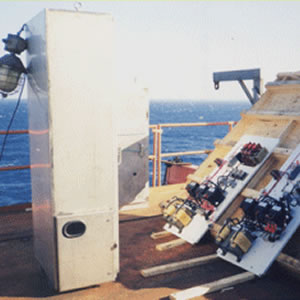
PLC
The PLC will monitor two injection pumps, two suction pumps, two filters, one desorption tower, two generators and six chemical pumps. The PLC will monitor the suction and discharge pressure of each injection pump as well as the normal pump shutdowns. The injection pumps are engine driven and the engines come with integral control panels to monitor and control the RPM of the engines, based on the discharge pressure. It will also shut down the engine on a pump shutdown or a pressure shutdown. The PLC will operate the selection of the filters based on a differential pressure reading across the filters. The PLC will monitor the tower level and operate a valve to control the level based on the suction pressure. There will be an operator interface on the main control cabinet and in a remote cabinet located on shore, and connected via a spread spectrum telemetry system. The operator interfaces will be able to change the programming and view the current conditions and set points. The PLC will come complete with the necessary communication ports to communicate with each components and with the telemetry system at a minimum, it will have enough 1/0 modules to support the following inputs: (9) Pressure transducers (2) 4-20ma electronic governors. (2) Electric valve (1) Actuated valve. (2)4-20ma magnetic pickups for engine RPM. (8) Digital signals from the two engine panels. (8) Digital signals from the injection pumps.
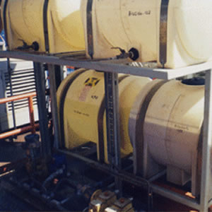
Chemicals
Six chemical storage tanks and six chemical pumps are provided. During normal operations, only two chemicals will be injected continuously. These are sodium hyprocholorite and an oxygen scavenger. Sodium hypochlorite will be injected into the lift pump water at the pump discharge head at the cellar deck. This chemical is a biocide to prevent slime and algae growth with the internals of the piping and vessels. This chemical will be injected at a rate of 2.5 ppm, or 3.15 gallons per day. A 55 gallon drum will last approximately 17.5 days. An oxygen scavenger will be injected into the water discharge of the ODT. It is anticipated that this injection rate will be up to 5 ppm or 6.3 gallons per day. A 110 gallon poly tank is provided for this chemical and will provide a 17 day supply. Two other biocides will be provided. These will be batch injected into the water on alternating weeks. The total volume of each chemical is injected over a 2-hour period every other week. One chemical biocide, an Aldehyde type, is injected between the filters and the ODT. The other chemical, a surfactant type, is injected between the ODT and the pump suction. The volume of each chemical injected is approximately 53 gallons per application.
Get In Touch
Headquarters Address
13 Mahdy Abdel Monem St.
Nasr City, Cairo,Egypt
Telephone: (202) 262-6434
Fax: (202) 263-6649
Email: alahlia@al-ahlia.com
Our Canadian Affiliate's Address:
601 200 La Caille Place S.W
Calgary, AB T2P 5E2 ,Canada
Telephone: (403) 206-1440
Fax: (403) 206-1450
Our Canadian Affiliate's Address:
601 200 La Caille Place S.W
Calgary, AB T2P 5E2 ,Canada
Telephone: (403) 206-1440
Fax: (403) 206-1450